Extended Components Library
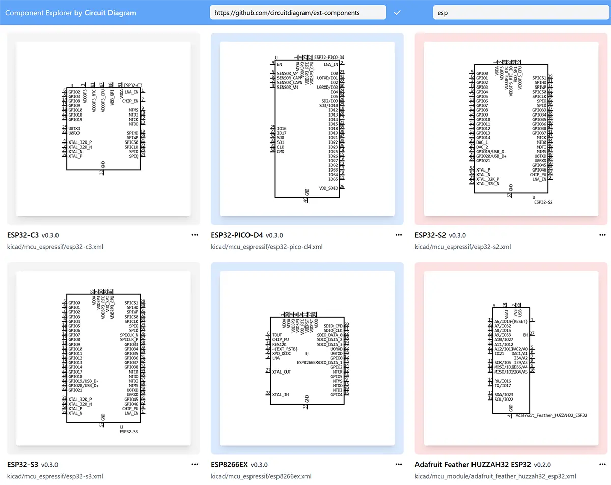
The Extended Components Library is a new project providing a additional component symbols to use in Circuit Diagram.
Find it on GitHub at circuitdiagram/ext-components.
All the latest news about Circuit Diagram. Read about new features, upcoming releases and more.
The Extended Components Library is a new project providing a additional component symbols to use in Circuit Diagram.
Find it on GitHub at circuitdiagram/ext-components.
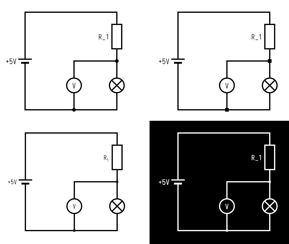
Circuit Shaders are a new way to extend the functionality of Circuit Diagram by adding effects and modifying the appearance of circuits.
Written in Python, they can do things such as:
Check out the available shaders in the Shader Gallery.
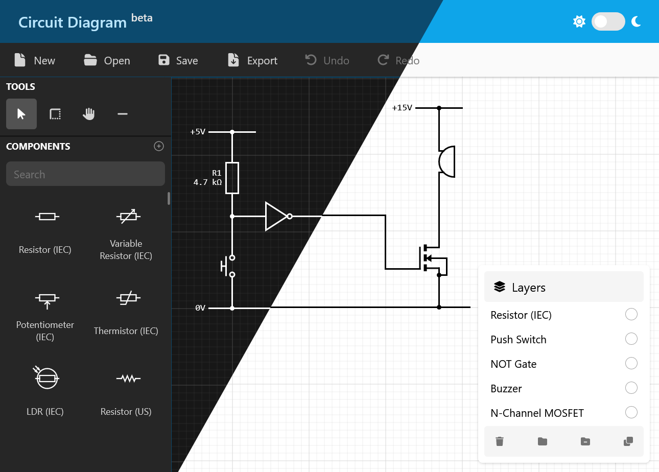
We are excited to announce a new version of the Web Editor has recently been in development and is now available to try in a closed beta.
The new Web Editor has been re-written from the ground up and features a number of improvements including a new dark mode.
To be among the first users to try the new editor, follow us on Twitter @Circuit_Diagram where we will be sharing invite codes to join the beta.
The Web Editor is regularly updated with new features and improvements. Here are a few of the new features that have been added recently.
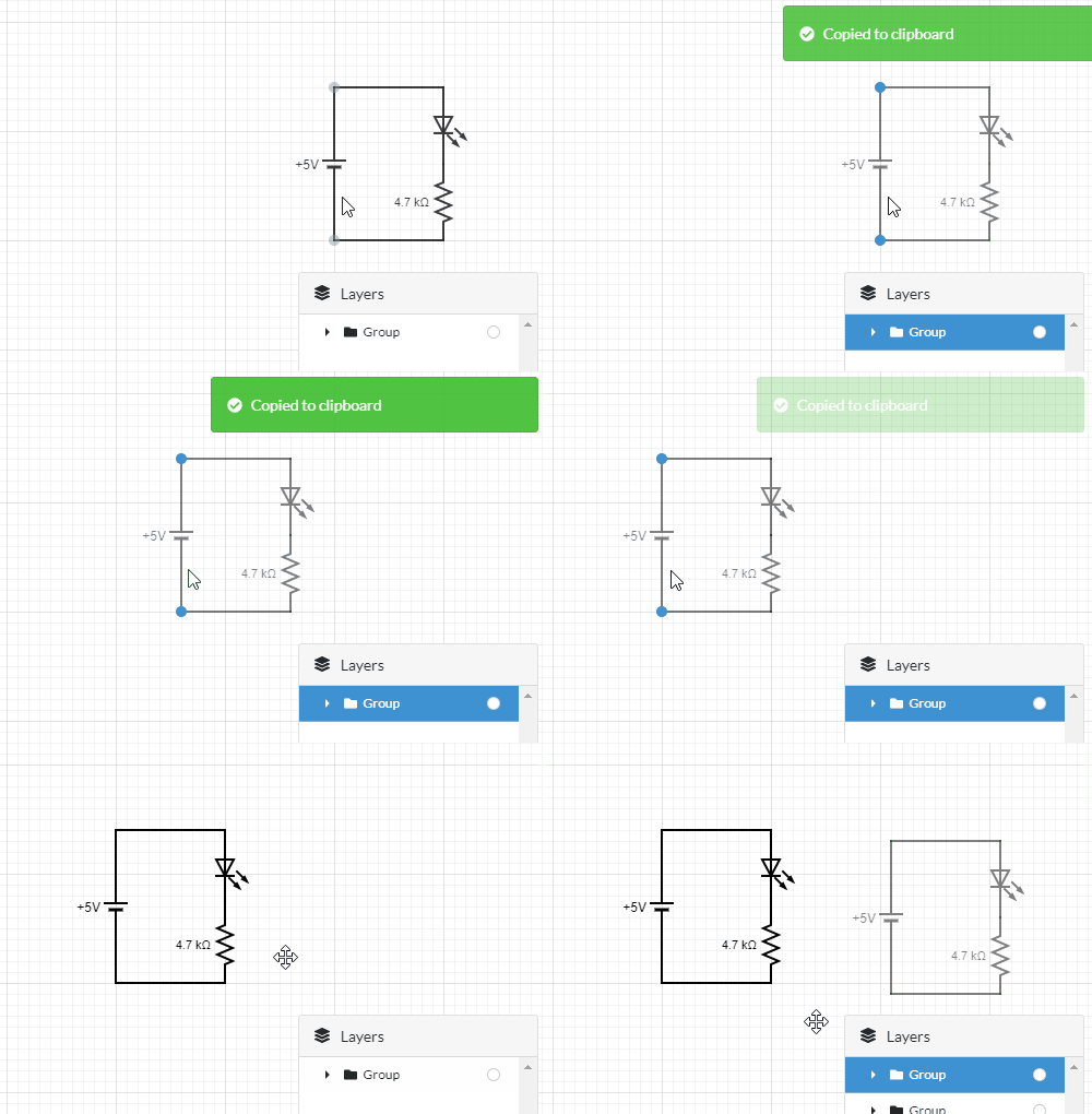
Cut, copy and paste components and layers between circuits using the keyboard shortcuts
Ctrl+X
, Ctrl+C
and Ctrl+V
.
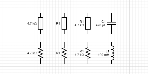
These components can now display both their text and value properties at the same time.
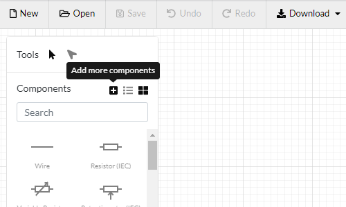
Many components are available by default in the Web Editor, but for even more, click on the Add more components button.
Circuits created using the Web Editor can now be viewed or exported as a circuit netlist.
Netists describe how components in a circuit are connected together, and are commonly used for circuit analysis, simulation and PCB design.
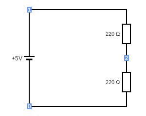
The circuit details page also shows a rendered view of the circuit with each of the netlist nodes marked on the circuit visually.
The above circuit is represented by the following netlist:
V1 1 0 5
R2 2 0 220
R3 1 2 220
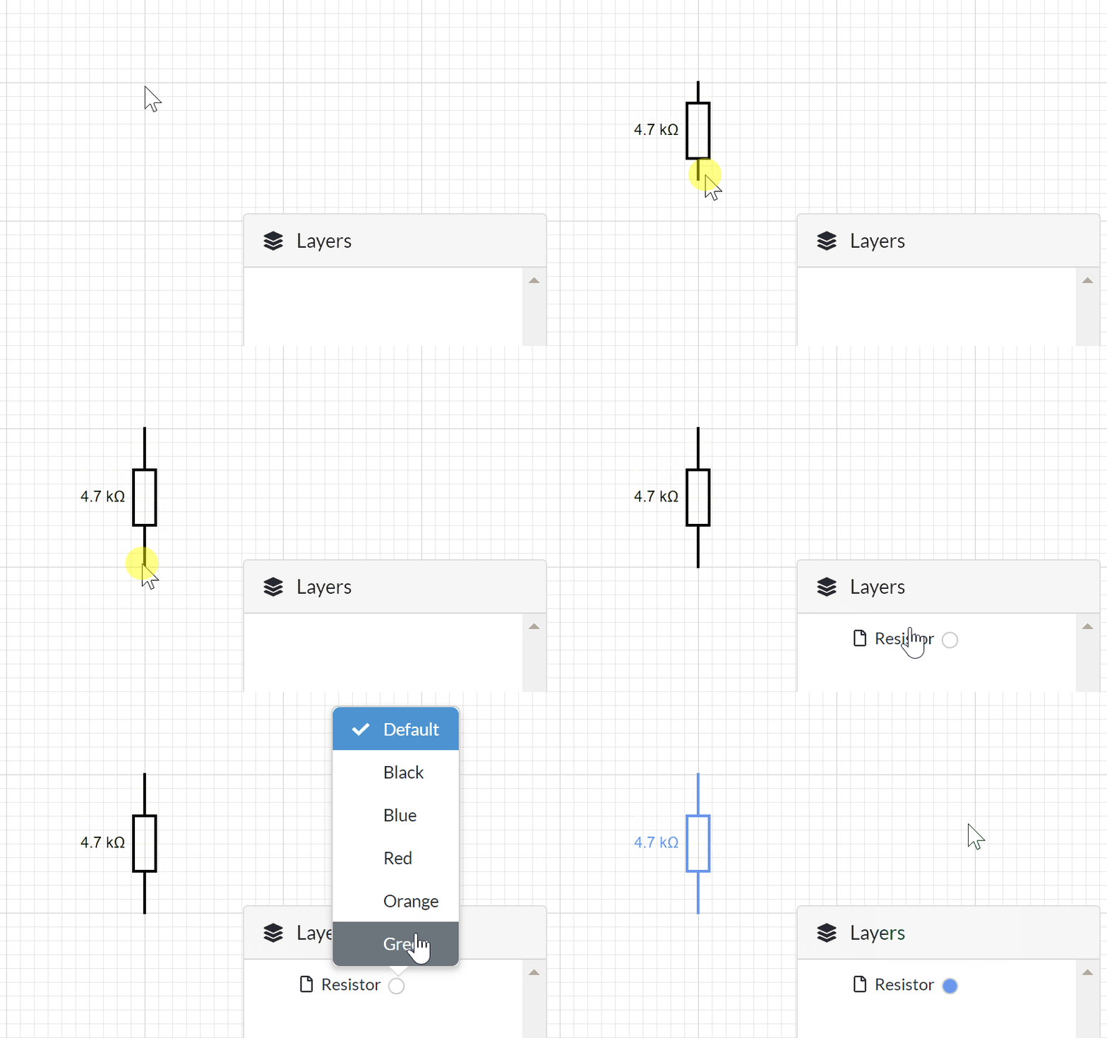
The Web Editor now supports creating color-coded circuits:
After placing a component, use the color picker in the Layers panel to set the color.
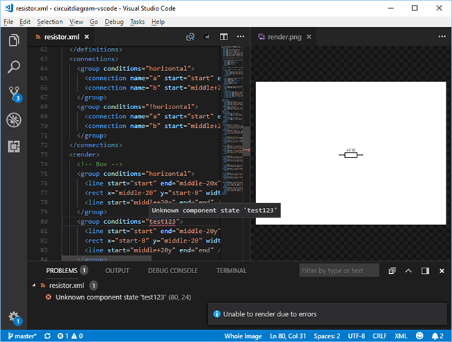
Build custom components in Visual Studio Code with the new VS Code extension.
As an additional option to using componenteditor.com, you can now use Visual Studio Code to create and edit custom components.
The extension is currently available as an early preview. It provides the following features:
Simulate your circuits using the new simulation functionality in the web editor.
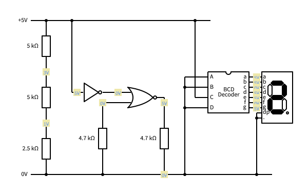
After clicking the simulate button, you will be presented with a snapshot of the simulated version of your circuit. This displays the voltages at all of the connection points in your circuit, and any components with dynamic behaviour will be rendered appropriately. For example, the Lamp will be lit if there is a voltage difference across it, and the 7 Segment Display will illuminate to show the input number.
Please be aware that this is a preview service and currently only supports a limited number of components. You might also experience some circuits that cannot be simulated while we are still working on improving this new feature.
Below is a copy of the simulation output from the Simulation Demo circuit:
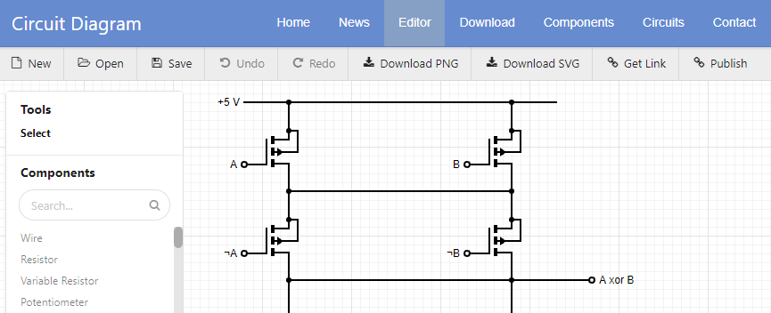
The web-based version of Circuit Diagram has been redesigned and is now available to use. The new and improved features are:
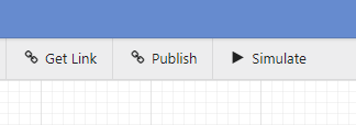
You can share links to circuits, and publish them on the circuits section.
Get link will provide a link to your circuit without listing it in the circuits directory.
Publish will make your circuit available for others to view in the circuits section.
You can now share circuit diagrams from the web editor by clicking the share link in the top right-hand corner.
From here you can share a short link to the circuit. For example:
There is also an html snippet to embed the circuit in another web page.